TECHNICAL DESCRIPTION.
B.1 General
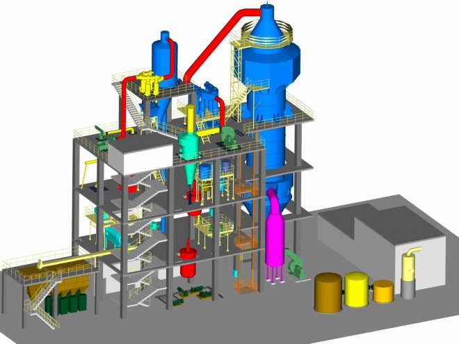
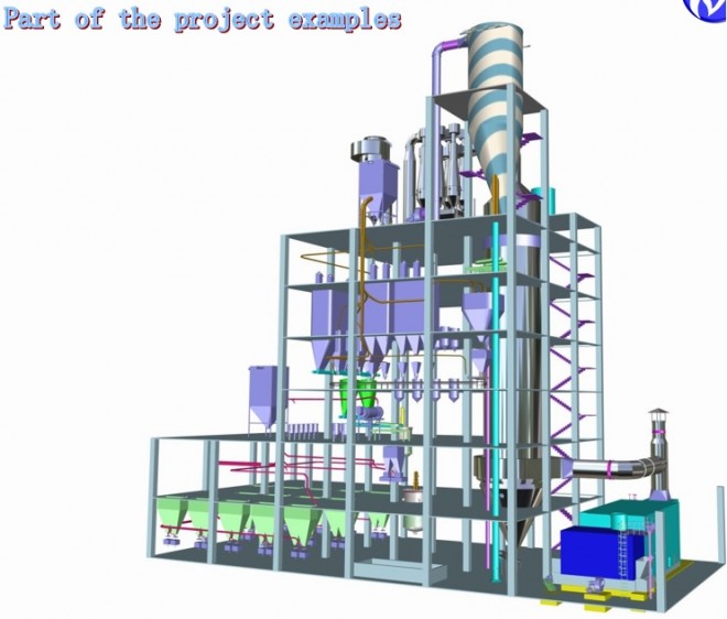
This is a semi-automatic washing powder factory that uses sulfonic acid as the main raw material to produce anionic detergent with the specified formula.
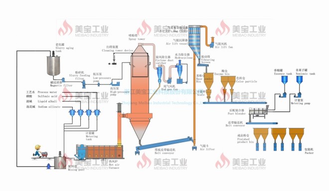
The plant includes Tank Farming (Section 100), Sludge Preparation (Section 200), Sludge Transfer (Section 300), Spray Drying (Section 400), and Post-Mixing (Section 500).
B.2 Process Description
B.2.1 Tank Farm (Section 100) (Buyer's Supplies)
Externally purchased dodecylbenzene sulfonic acid, packed in drums, manually loaded into the sulfonic acid unloading tank (101), then pumped to the sulfonic acid storage tank (103) by the sulfonic acid pump (102) . The caustic soda solution from the tank truck is loaded and unloaded into the Caustic Soda Unloading Tank (107) and then pumped to the Caustic Soda Tank (109) by the Caustic Soda Pump (108). Sodium silicate in liquid form is loaded into the Silicate Unloading Tank (104) then to the Silicate Storage Tank (106) by the Silicate Pump (105). Diesel is loaded into the Fuel Tank (110), and by the Fuel Pump (111) is fed to the Spray Dryer (Section 400).
B.2.2 Chuẩn bị bùn (Phần 200)
The sulfonic acid arrives by the Sulphonic Acid Pump (213) into the Head Container (204), and is then dosed in the Weigh Hopper for the Sulphonic Acid (206), while the caustic soda, process water and silicate enter the corresponding Head Container. their response (203,201 and 202), by the respective pumps, and quantified in the Weighing Funnel for Liquids (205).
The sulfonic acid was neutralized with caustic soda in a Crutcher (207), equipped with a strong stirrer. The resulting reaction forms sodium alkybenzene solfonate (the active substance). The two crutches work alternately.
Solid materials, such as STPP (sodium tripolyphosphate), sodium carbonate and sodium sulfate, CMC in bags are transported to the workshop and lifted by the Motor Hoist (214), moving along the overhead rail, up to the floor 3, where they are fed through a manual duct and by gravity fall onto the Crutcher (207) already loaded with other feed ingredients.
Contents can be mixed and heated. The slurry will then flow by gravity through the Mechanical Filter (208) and Magnetic Filter (209), and then to the Aging Tank (210), where it is aged and homogenized, ready to be sprayed. dried.
B 2.3 Sludge Transfer (Section 300)
The sludge is further homogenized in the Homogenizer Pump (301), and then fed into the High Pressure Pump (302). By the pump, the detergent slurry is transferred to the jets in the Spray Drying Section.
The recovered sludge is returned to the Crutcher (207) by Pump (305).
There are two sets of Homogenizer Pump and High Pressure Pump; when.
one set is active the other is in standby mode. The sets mentioned above have Mono-Pump (306) for each; The single pump acts as a booster pump to improve the efficiency of the homogenizer pump.
There is a Turbocharger Cylinder (303 A/B) to quench the surge.
B.2.4 Spray drying (Part 400)
The slurry is dried in a Spray Drying Tower (402) with hot air, which is prepared in a Hot Air Generator (407). Burner diesel fuel is used to generate heat. The hot air is diluted by the cool air provided by the Quench Air Fan (409).
The spray tower is working in an upstream manner. Detergent particles fall from above where the nozzles are located, and the hot air generated by the Hot Air Generator (407) enters the tower near the lower part of the tower. The detergent granules are dried and formed into hollow particles with a specified mass density and exit the tower on the Belt Conveyor at the Tower Bottom (411). Powder is transferred from here into the Air Duct inlet and is transported by the intake air by the Air Lift Fan (414), which moves up onto the Air Separator (412) where the powder is separated from the air and falls on the vibrating sieve (415). The target powder falls into the Product Powder Silo (513 A/B/C/D) in the Post-Mixing Section.
The exhaust air is sucked out at the top of the tower by the Exhaust Fan (406). The air containing the cleaner will be separated from the impurities contained in the Exhaust Cyclone Unit (405) and the Exhaust Air Bag Filter (416) before being released to the atmosphere. Fines collected in the device are discharged by gravity for recycling.
The air coming out from the top of the Lift Air Separator (412), containing the cleaning agents, is filtered out in the Air Bag Filter (413) on the top of the separator, before it is vented to the atmosphere.
B.2.5 Shuffle (Part 500)
In this section, the base powder is mixed with heat-sensitive solid and liquid ingredients, e.g. perborate, CMC, non-ionic, perfume, etc., so the product washing powder will meet the specified formulation.
The Base Powder from the Vibrating Sieve (415) is stored in the Basic Powder Bucket (501). From there, the basic powder is quantified using the Basic Flour Weighing Belt (502). Perborate, from Perborate Bin (503), is quantified by a separate Perborate Belt (504). The base powder and the perborate powder are then combined by gravity into the Post Mixer Rotary Mixer (509). Liquid ingredients, e.g. nonionic, perfume dosed by Nonionic Dosing Pump (506) and Perfume Dosing Pump (508) are loaded with respective kettles, respectively, sent into the same rotary mixer (509). The solid and liquid components will be mixed together in it. The mixed powder from here is transported by the Delivery Belt (512) and taken to one of the Product Powder Silos (512A/B/C), ready to feed to the packer. That's three bagging machines and one other people's canning machine.
There is a dust extraction system that sucks in dusty air to be filtered out, before being released into the atmosphere
.
B.3. Specification of feed ingredients and products
B.3.1 Specification of feed ingredients
B.3.1.1 Dodecylbenzene sulfonic acid (DDBS)
Sulfonic acid 96% min.
Maximum sulfuric acid 1.2%.
Free oil up to 0.9%.
Water 1.2% max.
Average molecular weight 366
Neutralization value 128 mg NaOH/mg sulfonic acid
Appearance Dark brown liquid.
B.3.1.2 Sodium hydroxide of commercial grade
Sodium hydroxide 95% min.
Sodium carbonate up to 3.0%.
Chloride (as Cl) 0.01% max.
Sulfate (as SO4) 0.02% max.
B.3.1.3 Sodium tripolyphosphate (STPP)
Appearance White and Clean
P2O5 content 56% min.
Water insoluble up to 0.1%.
pH (1% solution) 9.5 to 10.1
Minimum STPP content 90%.
B.3.1.4 Sodium sulfate
Na2SO4 content 98% min.
Water insoluble up to 0.5%.
Total calcium and magnesium (as Mg) 0.15% maximum.
Chlorite (as Cl) up to 0.3%.
Iron (as Fe) up to 100 ppm.
Maximum humidity 0.5%
pH 7 to 9
Color 80 minutes.
Sieve (250 m sieve) 10%
B.3.1.5 Sodium silicate
SiO2 / Na2O Module 2.2 to 2.5
Density (at 20C) 40 to 42 Be"
Sodium oxide (Na2O) content 9.5% min.
Silica (SiO2) content 22.1% min.
Iron (Fe) 0.02% max.
Water insoluble up to 0.2%.
B.3.1.6 Sodium carbonate
Total alkalinity (as Na2CO3) is at least 98%.
Maximum sodium chloride (NaCl) content 1.0%.
Iron oxide (like Fe2O3) 0.01% max.
Water insoluble up to 0.5%.
Maximum fire loss 0.5%.
B.3.1.7 P-Toluene sulfonate.
P-Toluene sulfonate content 79% min.
Inorganic salts up to 9%.
Maximum humidity 4%.
pH (12% aqueous solution) 9 to 10
Chloride maximum 2.5%.
Sodium sulfate up to 5%.
B.3.1.8 Carboxymethylcellulose (CMC)
2% aqueous solution viscosity 1200 Cp min.
Sodium (Na) 6.5 to 8.5%
Ph 6.5 to 8
Maximum humidity 10%.
Chloride (as NaCl) up to 3%.
Heavy metals (such as Fe) 0.03% max.
Arsenic (As) up to 0.0002%
B.4 Product Powder
TYPICAL DISPOSAL POWDER
TAB. B.4.1 TYPICAL DETERGENT POWDER FORMULATION (1)
Bulk density 350 g/L
| Item No. | Ingredient | Percentage (%) | Remarks |
| 1 | LAS | 10 | |
| 2 | STPP | 16 | |
| 3 | Nonionic | 2 | |
| 4 | Sodium sulfate | 36 | |
| 5 | Sodium silicate | 12 | |
| 6 | Sodium carbonate | 8 | |
| 7 | Soap | 2 | |
| 8 | CMC | 1 | |
| 9 | Brightener | 0.1 | |
| 10 | Sodium Toluene sulfonate | 2 | |
| 11 | Enzyme | 5 | |
| 12 | Perfume | 0.1 | |
| 13 | Moisture | 5.8 | |
| | Total | 100 | |
TAB. B.4.2 CÔNG THỨC BỘT KHỬ MÙI TIÊU BIỂU (2)
Bulk Density 280 g/L
| Item No. | Nguyên liệu | Phần trăm (%) | Nhận xét |
| 1 | LAS | 21 | |
| 2 | STPP | 21 | |
| 3 | Sodium carbonate | 3. | |
| 4 | Sodium sulfate | 38 | |
| 5 | Sodium silicate (on dry basis) | 9.2 | |
| 6 | CMC | 1 | |
| 7 | Sodium P-toluene sulfonate | 1.5 | |
| 8 | Perfume + Alcohol | 0.25 | |
| 9 | Moisture | 5 | |
| | Total | 100 | |
B.5 Utility Requirements
Coolant
Maximum temperature. 30 C
Increase the temperature approx. 7 C
Minimum pressure. 3 bars
neutral pH value
Maximum chloride content. 60 mg/l
No solids.
Electric Energy
3 phase AC 3 PNE 50 Hz
Service voltage 220/380 V AC
Accepted variations:
voltage 5%
Frequency 3%
Steam
Minimum pressure. 3 bars
Saturated and dry
Instrument
Minimum pressure. 6 bars
Maximum particle size. 5 m
Particle density max. 1 mg/Nm3
Maximum oil content. 1 mg/Nm3
Minimum dew point. -20 C
B.6 Economic and technical parameters
B.6.1 Capacity of one (1) t/h of product cleaning powder when the plant is in normal operation.
B.6.2 Operating conditions
Operating data (for reference only)
Sludge concentration (%) 60 to 65
Sludge temperature (C) 65 to 70
Injection pressure (bar) 20 to 40
Hot air at the inlet of the Drying Tower (C) 300 to 360
Hot Air Temperature at Hot Air Generator outlet (C) 320 to 380
Exhaust gas temperature (C) 90 to 95
Negative pressure at the top of the drying tower mm H2O -5 to -10
Negative Pressure in Hot Air Generator mm H2O -1 to -3
B.6.3 Raw Material Consumption
Sulfonic acid per kg of LAS (sodium dodecylbenzene sulfonate) active agent: 970 kg
Caustic soda/kg active substance (LAS): 120 kg (dry).
Others depend on the detergent formula,
B.6.4 Utility consumption per ton of finished powder
Electric capacity approx. 60 kWh
Steam max. 100 kg
Maximum water treatment. 1,300 kg
Tool max. 0.3 Nm3
Diesel oil 60 kg
all utilities must be understood as the mean value (tolerance 8%) for continuous uninterrupted operation with one and the same supply and a constant and uniform supply of utilities.
B.7 Wastewater No liquid waste is discharged during the normal operation of the plant.
Exhaust gas is air from filters in different zones, however, max. The dust content in these air streams is a maximum of 100 mg/m3.
B.8 Control system
The plant is controlled by conventional equipment.
The vendor's scope of supply includes field instrumentation and system hardware.
B.9 Electrical system
The electrical system includes:
- Power distribution board
- Electric scooters
- Power distribution cables and accessories
B.9.1 Power Distribution Board
It includes device to control and protect all power users within Battery Limit.
The control panel is of the cabinet type, made from rigid panels that can be easily extended with movable shoulders.
Outdoor panel protection is IP41, while indoor protection is IP20.
The control panel also includes a 380/220V transformer (or 380/110V on request) for the control and auxiliary circuits.
The lamp will be powered at 24 V A.C.
Control panel includes:
- Selector switch for connection or control and associated signal lights
- Remote control switch
- Heat protection
- Power fuse and auxiliary fuse
- Star-delta starters for engines over 22 kW and DOL starters for other engines
- The main lever
- Voltmeter
- Ammeter
- Terminal board for connecting power cables
- Provide local console (if available)
Motor start/stop can be done via power distribution panel selector switches or through the monitoring system workstation.
B.9.2 Cable
Distribution cables will be multi-core, PVC-insulated R2 Class 4 quality suitable for normal voltages up to 500 V A.C.
The cables will be installed inside the cable tray for main running and put into the conduit to connect from the cable tray to the user.
B.9.3 Accessories
Fittings means all materials for the installation connections of cables, i.e. cable trays, conduit and fittings.
Building B.10
The floor area is about 800 square meters.
SELLER SUPPLIER DOCUMENTS.
C.1 Technical
Seller will provide basic design and detailed design in Battery Limits.
The technical documents will be in English, use the metric system and conform to the standards/codes listed in Para.
Seller will provide two copies of the following documents:
C.1.1 Basic Design
Process Description
Material balance
Design Facility
- Factory capacity
- Product features
- Material specification
- Chemical specification
- Catalyst specification
- Wastewater
- Raw materials, chemicals and catalyst consumption
- Battery limit status
Utility Data
- Consumption of utilities
- Battery limit status
Equipment and machinery
- List of devices
- Machine specifications
Pipe
- Line list (process flow)
- Pipeline class
Instrumentation
- List of tools
- Tool data sheet
Electricity
- Download list
Drawings
- P&I chart
- Preliminary overall payment of the factory
- Factory floor plan
C.1.2 Detailed Design
C.1.2.1 Piping
Plot map (and sections)
Open on slab
Utility map
Single line diagram with load for steel structure
Piping layout
Floor plan and wall openings (with load and anchor bolts)
Arrange underground pipelines.
General Pipeline Support Plan
Summary of Pipe Material
C.1.2.2 Equipment design
Device Specification Sheet (final)
Construction drawings (provided by buyer only)
Calculation diagram (for officially approved equipment)
C.1.2.3 Electrical Design / Instruments
Tooling specification and schedule
Wiring Diagram
Process sketch, electrical/pneumatic connection
Tool layout
Erection materials and cable list
Load list and a flow chart
Electrical panel specification and wiring diagram
Power distribution arrangement
Pneumatic motors are designed for long service life and harsh operating conditions.
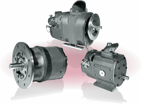
Reliable in wet environments and harsh climatic conditions.
These 'air' engines can operate on air, nitrogen and other gases. Equipped with an inlet filter, differential pressure lubricant and an adjustable speed limiter as standard. Special versions for operation with non-lubricating air are also available. The built-in sound insulation can be improved with a downstream silencer. The rotors are hardened and grounded to ensure a long service life.
Benefits/characteristics
» Adjust engine rpm by easy throttle control.
» Change direction by check valve with manual or remote control.
» Higher starting torque at full power.
» Differential-pressure-oil for long-term operation and humid air.
» Special construction to operate with oil-free air.
» Overload without time limit also stands still.
» Especially suitable for operation in explosive atmospheres.
» Solid construction ensures high operational security.
» Long life due to hardened and grounded propellers.
» Good silence due to long air outlet.
» Additional silencer available.
» IEC shaft and flange dimensions according to DIN 42677 waterproof.
» Standardized flange and shaft dimensions are interchangeable with electric motors.
These pneumatic motors have been designed for long service life and harsh operating conditions. They also work reliably in wet environments and harsh climatic conditions. Comply with ATEX for use in hazardous areas. The engine can be operated with air, nitrogen or other gases. As standard, they are equipped with a protective filter pad, a differential pressure boiler and an adjustable rev limiter. Special version for operation with available air. Good sound absorption is ensured by the long exhaust routing process, which can also provide additional downstream muffler. The rotors are hardened and grounded to ensure a long service life.
» Geometric displacement 155-6116 cm³/rev
» Operating pressure up to 10 bar
» Capacity 2.8-66 kW
» Torque 9-420 Nm
» Speed range up to 3000 rpm
» Air consumption 3.9-66 Nm³/min
Specifications for PMW160 - PMW530 . series
Pneumatic engine with exhaust gas throttle.
Capacity 2.8 - 8.5 kw
» Especially suitable for operating in explosive atmospheres.
» Solid structure ensures high operational security.
» Long life due to hardened and ground rotors.
» Good silence due to long discharge path.
» Adjust rpm by easy throttle control.
» Change direction by check valve with manual or remote control.
» The starting torque is higher than the maximum torque.
» Safe in wet environments and harsh climatic conditions.
» With oil filter for long-term operation and humidified air.
» Additional silencer available.
» Works with gas, air, nitrogen.
» Special construction to work with oil-free air Waterproof.
» Overload without time limit also stands still.
» Standardized flange and shaft dimensions compatible with electric motors.
» IEC flange and shaft dimensions according to DIN42677.
» Links to application examples. » Link to order code information. » Link to a wide range of accessories available for PMW series and DMO series pneumatic motors.

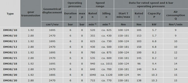
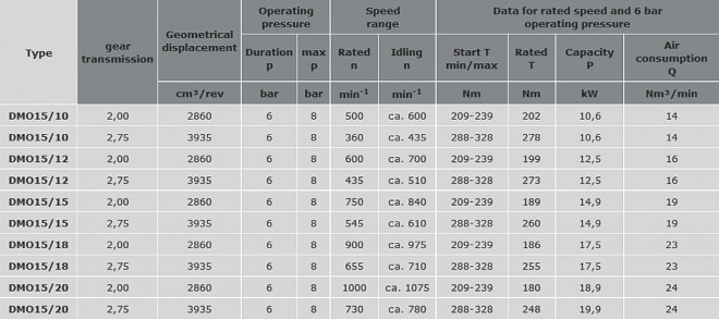
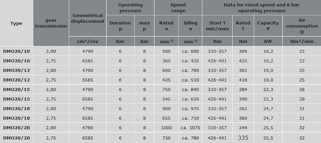
Specifications for DMO8 - DMO20 series (3 tables below)
Pneumatic motor with speed limiter.
Capacity 3.6 - 28.1 kW
With speed limit from 1000/min to 2000/min (DMO ... / 10.bzw. DMO ... / 20)
The DMO Pneumatic Gear Motor is designed for long-term operation under extreme conditions. Air, nitrogen or a similar gas mixture is supplied to the engine through a hose or DN50 pipe. At medium temperatures, we recommend a maximum temperature value of 60-70°C. Ambient or radiant heat should not exceed 70-90°C.
For different temperatures please contact our technical department by phone: 01737 767493 or email: info@jbj.co.uk
» Links to application examples. » Link to Calculus
compressed air tank volume for example emergency drive.
» Links to a wide range of accessories available for PMW series and DMO dòng series pneumatic motors


